What are Solid State Relays and How Do They Work?
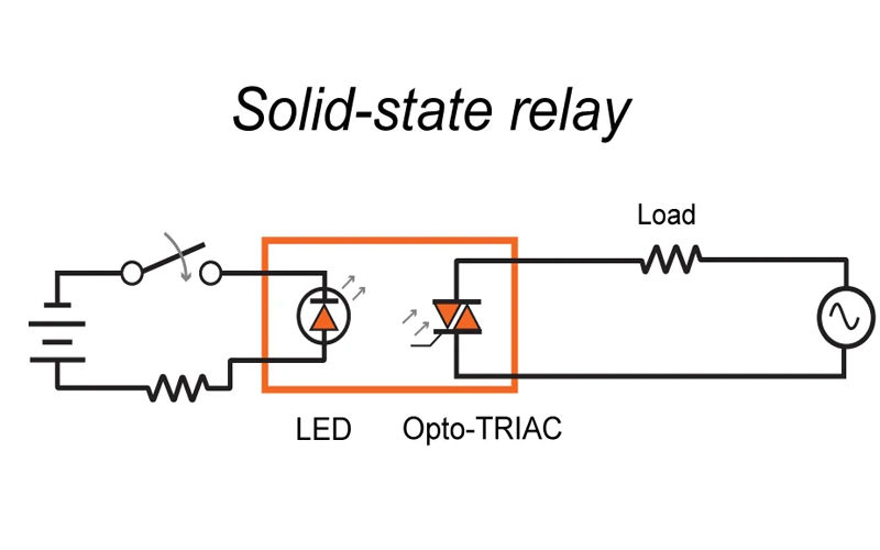
SSR is a kind of electronic component(or Non-Contact Switch) that consists of Microelectronic circuit, discrete electronic devices, and electronic power components. It utilizes an isolator to achieve segregation between the control and load circuits, where SSR can activate a high level of current load by a weak signal at the input terminal. Thus, solid state relay not only are compatible with logic circuits with low watt and electronic noise but also have the functions of an electromagnetic relay. Generally speaking, the types of heatsinks are determined by load current and ambient temperature of relay SSR.
Concerned Technical Issues When Installation
Ambient Temperature
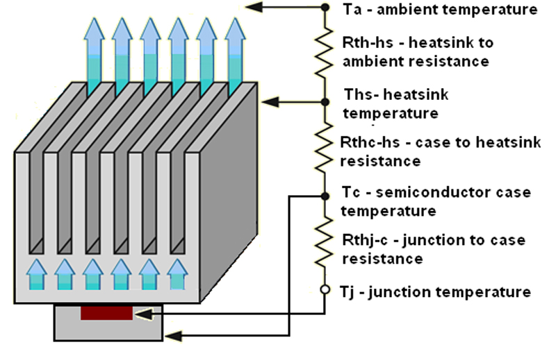
Keep in mind that do not put your SSR into a high-temperature condition that causes under-performance heat dissipation. Typically the LED junction temperature should be between -40°C and 100°C and not exceed 150°C. Also, be aware of the surrounding air temperature and pressure while installing thermal pads or over-temp protection devices.
Heat Dissipation
In addition to the external temperature mentioned above, power loss is likely to happen inside the chip during ordinary operation. The heat generated by this power loss is mainly determined by the output voltage and load current performance of solid state relays. Therefore, heat dissipation will directly affect the reliability of SSR operation while outstanding thermal design can avoid negative effects caused by poor heat dissipation.
Electrical Noise
Generally speaking, electrical noise does not cause deficiency of solid state relay despite any errors occurring in circuits and triggering an excessive current surge. However, there are reasons for generating electromagnetic noise, such as vibrations in motors, power supplies, motors, etc. Or, provided a sudden disconnection of fuses, ultraviolet light or ultrasonic waves emitted via metal surfaces from arcing motor control circuits can cause SSRs to generate electrical noise.
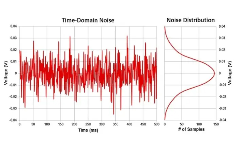
Essentially, it seems that this phenomenon should be more accurately defined as electromagnetic interference (EMI), which affects circuits in a way that feeds electrical energy detectors or normally open contact. For example, SCR(or Thyristor)
MOV-Metal Oxide Varistors
Given excessive heat, instantaneous current, breakdown voltage, etc, high-level load current will damage solid state relay dramatically, MOV is installed together with SSR to avoid accidents. Currently, MOVs are used in 2 main ways respectively: suppressing external transient currents before flowing into the component;
1, Suppressing external transient currents before flowing into the component.
2, choosing a larger MOV load to suppress the transient current and heat
MOV can be effectively used for loads such as transformers and switching watt supply lamps. Since the peak currents are absorbed by the MOV, it can greatly extend the life of the device and provide a low-cost protective solution for the solid state relay.
Rated Value of Surge Current and Rising Rate
In addition to thermal problems caused by surrounding temp, surge current(Inrush current) is one of the most common reasons for SSR failures. When acquiring a new batch of electronic equipment, you should first check the current load, which will be mentioned in the equipment manual. Or, you also can contact a professional SSR heat sink manufacturer. In general, the maximum surge current rating of an SSR is 10 times RMS value in steady state, which is the maximum peak current for a line cycle.
However, it is important to note that a properly functioning SSR can withstand surge currents within 100 times. Additionally, surge currents will cause the SSR to lose control of current. Whereas, wait a few seconds until the thyristor’s blocking capability and the component’s junction temperature return to a steady state.
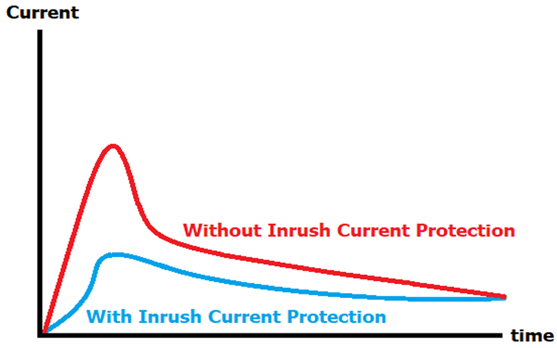
Except for the rated value, the rising rate of the surge current (di/dt: amps per microsecond) is also an important factor in the installation of thyristor-type relays. In particular, the rising rate with high speed leads to faults in the over current protection circuits or an overshoot of output voltage.
Fuses
As output elements of solid state relays, SCRs are ineffective for protection circuits that exceed the tolerance value of the SSR surge current or short circuit current up to 10Ms (50Hz) for its Over Zero Shutdown. In this case, a current-limiting fuse should be installed, whose nominal fusing current should not exceed the value of SSR while providing a very fast disconnection speed.
Installation Tips for Solid State Relay Heatsink
Installing SSR Heat Sink
All solid state relays generate heat. The heat will cause the solid state relays to reduce (or derate) the load current it can withstand when heatsinks are not installed. Conversely, Aa heat sink with good thermal performance can directly affect the maximum load current. Here are the following measurements for you to determine if your electronic components need to be equipped with a heat sink:
Below 10A: Equipped with a good thermal performance of the electronic instrument base plate (thermal pad)
Above 10A: Equipped with passive solid state relay extruded heat sink
Above 30A: equipped with fan solid state replay heat sink
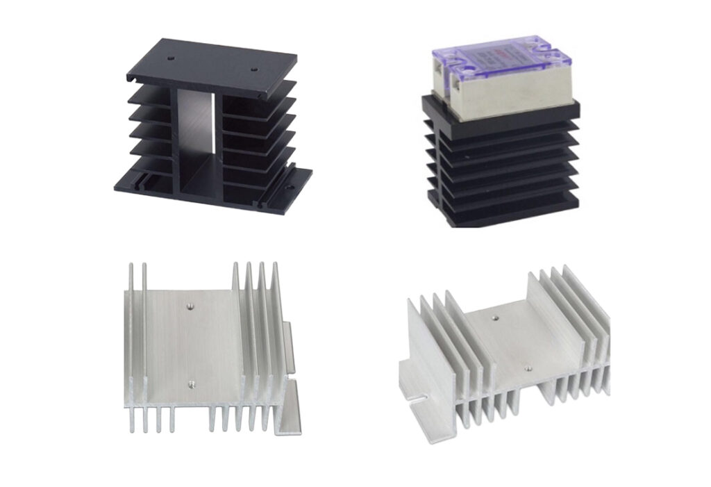
If you don’t know how to choose a suitable heat sink, you can check how to influence the cost of heat sink or consults a professional custom heat sink manufacturer.
SSR Heat Sink Placement
Heat sinks should be vertical mounting to ensure unimpeded air circulation. To avoid dust falling into heatsink unit, SSRs should be placed in an ideal environment against dust while ensuring unimpeded air flow is permitted by separating around each SSR for 100% performance. Due to confined area, its nominal current should be reduced by 30% to ensure the electrical enclosure is not affected by heat.
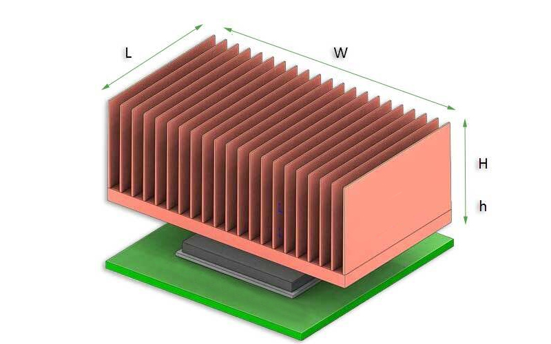
The thermocouple-the best tool to detect the surface temperature of enclosure. First, insert the probe pin into the mounting screw then see if its temp exceeds 45°C based on normal operation; If the answer is not, install it with a more suitable heat sink or use a fan to provide the best air flow. In any condition, thermal derating is required for SSRs with higher output currents.
Thermal Interface
The thermal interface (TMI) of heat sink can improve the heat transfer between the relay and the heat sink. Since there is a slow air flow in the cavity which is not sufficient for heat transfer, the gap should be filled with thermal grease or installs a thermally conductive panel that speeds up the heat transfer. Before doing this, make sure that the surface of the solid state relays heatsink is clean enough (or no painted surfaces and surface roughness less than 100µm). When everything is ready, Let’s get started. First, apply thermal grease to the metal surface with a thickness of 50-100µm without covering the heatsink completely.
Tightening Torque
After applying thermal grease, it is recommended to slow down the speed of screw installation so that it spreads evenly between the gaps. Conversely, denser thermal grease and tightening the screws at high speed causes damage to the screw holes in the heatsink. Therefore, the maximum screw speed should not exceed 250 rpm against internal stress, which is why we accentuate the importance of torque overshoot.
